A Systematic Approach To Deep Hole Drilling
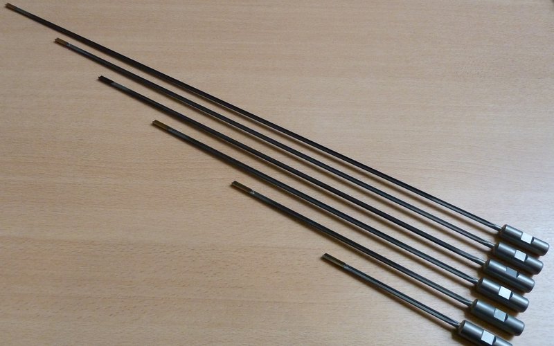
The most basic form of internal machining is drilling. In drilling terms, holes with a diameter between 0.2 and 500 mm and a drilling depth typically greater than three times the diameter are generally considered to be ‘deep’ holes.
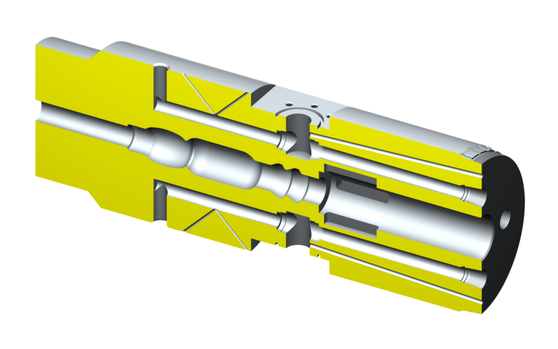
Special challenges call for special tools
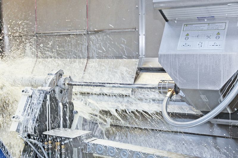
The perennial challenges associated with deep hole drilling are how to introduce cooling lubricant to the cutting edge, how to remove swarf at a steady rate, and how to create the straightest possible hole. With deep hole drilling procedures, the drilling head next to the actual main cutting element (mostly an individual cutting edge or one made up of interchangeable cutting inserts) consists of a secondary cutting edge and additional guide strips. This arrangement ensures the drill bit is supported at the wall of the hole, which increases accuracy and makes it easier to centre the drill bit during the process. The support provided to the drill bit also produces a smoothing effect, which improves the surface quality inside the hole.
Different processes
Deep hole drilling processes are divided into two main categories, depending on whether chips are removed externally or internally. External chip removal is mainly associated with gun drilling and, more rarely, double-lip deep hole drilling, whereby cooling lubricant is introduced to the cutting edge via inlet holes in the drill bit and the chip/cooling lubricant mixture is transported away along a V-shaped longitudinal slot in the tool. This process is typically used for drilling diameters between 0.5 and 40 mm. Another option, at drilling diameters of 16 mm and above, is the BTA process. This is one of the processes whereby the chip/cooling lubricant mix is transported away internally. The advantage with processes where chips are transported away internally is that outgoing chips no longer come into contact with the surface of the hole and therefore cannot damage it. Ejector drill bits, a special form of BTA bit, may be used at diameters of approximately 25 mm and above based on a two-pipe arrangement. These drill bits have additional cooling lubricant outlets around the edge of the drilling head, and some of the lubricant is fed directly into the internal pipe through a ring nozzle. This creates negative pressure in the front section of the drill bit, which accelerates removal of the chip/cooling lubricant mixture.
Integrated machining
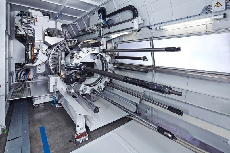
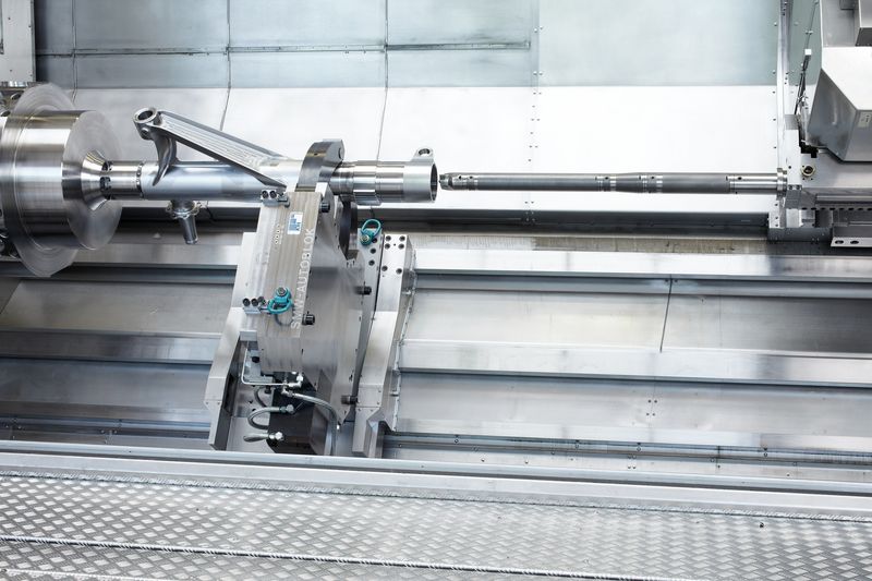
With extremely deep holes or materials where machining is difficult, excessive tool wear often requires that drilling is performed in stages using tools of different lengths but the same diameter. WFL MILLTURN machining centres offer decisive advantages as far as these kinds of machining steps are concerned. For one thing, the various drilling tools used can be stored and kept ready in the tool magazine; this minimises interruptions and manual processes while significantly improving positional accuracy. Not to mention the fact that genuine six-sided deep hole machining can only be performed during one clamping operation or two at the most.
Automatic workpiece measurement and adaptive control
Due to the large tool projection, deep drilled holes are subject to hole centre deviation that increases with the hole depth. These machining errors cannot be fully eliminated, even when machining on MILLTURN machines. Hole centre deviations are measured by intelligent in-process measuring following the completion of deep hole drilling. This is performed either with an extended measuring probe or by means of ultrasonic wall thickness measurement, which involves measuring the thickness of the wall at various circumferential positions and calculating the middle of the centre hole. New clamping points are then produced on the workpiece concentrically to the defective deep drilled hole by means of turn-milling. This allows the realisation of all subsequent machining processes with very close form and position tolerance to the deep drilled hole. The benefits are clear. Set-up times are reduced enormously and any finishing work due to deformation resulting from other work steps can be carried out immediately. Process steps can be carried out consecutively without having to compromise on accuracy.