Measuring technology (Part 2)

In order to meet today‘s requirements, it is important to make measuring an integral component of forward-looking production processes. The closed-loop approach attempts to make the network consisting of production system, machine, operator and measuring technology as simple and efficient as possible. One of the most important elements in this network is measuring during the production process.
Before a measuring probe can be used to take a measurement, it must be calibrated. This is usually performed by the operator before the start of a machining process. Calibration can also be carried out fully automatically via the NC programme.
After touching the surface with the stylus, a measuring probe must experience a certain deflection before the switching signal is sent to the machine control system. This pre-travel is not known a priori and is dependent on the length of the stylus, the feed direction, etc. but can be accurately reproduced.
The pre-travel does not need to be known for many standard measurement methods, for example measuring the depth of a milling pocket. When the measuring probe touches the reference surface and the bottom of the pocket, the difference between the two switching points reveals the exact pocket depth - even without calibration - as the two measuring points are approached with the same feed direction and the corresponding pre-travels cancel each other out when the difference is formed.
If, however, features such as the width of a milling pocket or a shaft diameter are to be measured with the Y-axis, opposing surfaces on the workpiece must be approached with the opposite feed direction and the difference between the switching points must be determined. To obtain accurate measured values in this case, it is necessary to calibrate the measuring probe, i.e. to know the precise pre-travels.
Calibration is only possible if the expected target value is known. Calibration can be carried out either at any point or using a calibration device. The measuring probe can be calibrated at any diameter, with a calibration ring or a special jig.
Calibration with a jig simplifies the calibration process, as the target value is already known and is stored with the corresponding machine data in the control system.
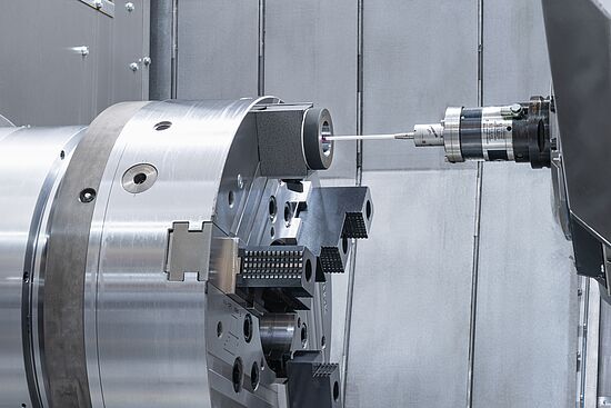
Calibration device on the tailstock of the M200 MILLTURN incl. temperature compensation
Temperature-stabilised water from the coolant system flows through the calibration device, which is mounted on the tailstock in the direction of the Y-axis and has a cover which prevents ingress of dirt into the measurement room.
In the middle of the calibration device, there is a cuboid on which the switching points of the measuring probe can be determined in the X1, Y1 and Z1 direction. Up to 12 measuring points are also fitted at which distances of different lengths can be calibrated. Two temperature sensors are used to automatically record the current temperature of the calibration device and the machine bed. Calibration at the 12 measuring points enables the current thermal expansion status of the measurement system for machine axis Y to be accurately determined. This is particularly important with large workpiece diameters. The thermal expansion of the measurement system in the X and Z direction is taken into account using the measured temperature for the machine bed and the known expansion coefficients for the measuring systems.
Calibration of the measuring probe on the calibration ring.
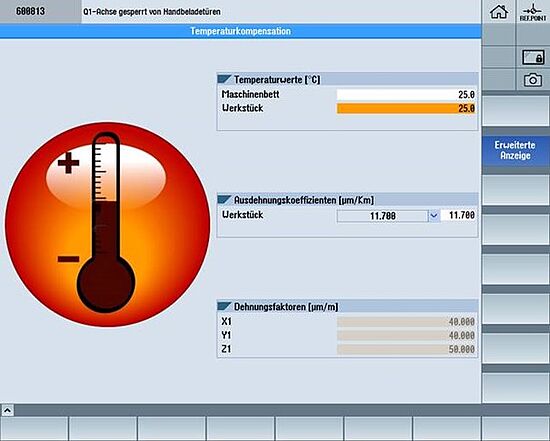
The WFL measurement and correction cycles ensure that the measurement results from the machine now match the actual dimensions of the workpiece at a standard temperature of 20°. If tools or positions are corrected, the temperature compensation/ back calculation to the standard temperature of 20°C is beneficial for the achievable accuracy.
A portable measurement device is supplied for recording the workpiece temperature. Right before the final machining of a tight fit, for example, a menu screen can be automatically displayed via an NC subprogramme. This prompts the operator to measure the current workpiece temperature and enter it on the screen.
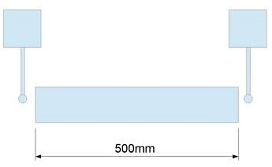
Example:
The 500-mm-long shaft with a temperature of 26°C is measured in the machine. The machine temperature is 20°C. Since in this case the workpiece has reached excess temperature, it expands and too large a measurement is measured. Without temperature compensation, the actual length is 500.033 mm.
Temperature expansion coefficient workpiece = 11 μm/Km
Temperature expansion coefficient measuring ruler = 8 μm/Km