Ultrasonic measurement
Automatic ultrasonic wall thickness measurement is used for precise quality monitoring as well as position determination of inside to outside diameter (concentricity) for tube-shaped workpieces for which the measuring point cannot be reached with conventional workpiece measuring probes.
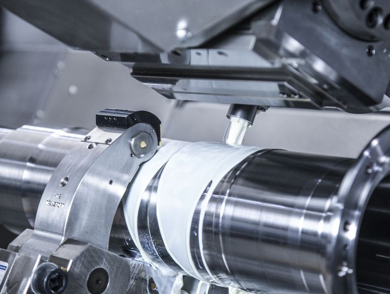
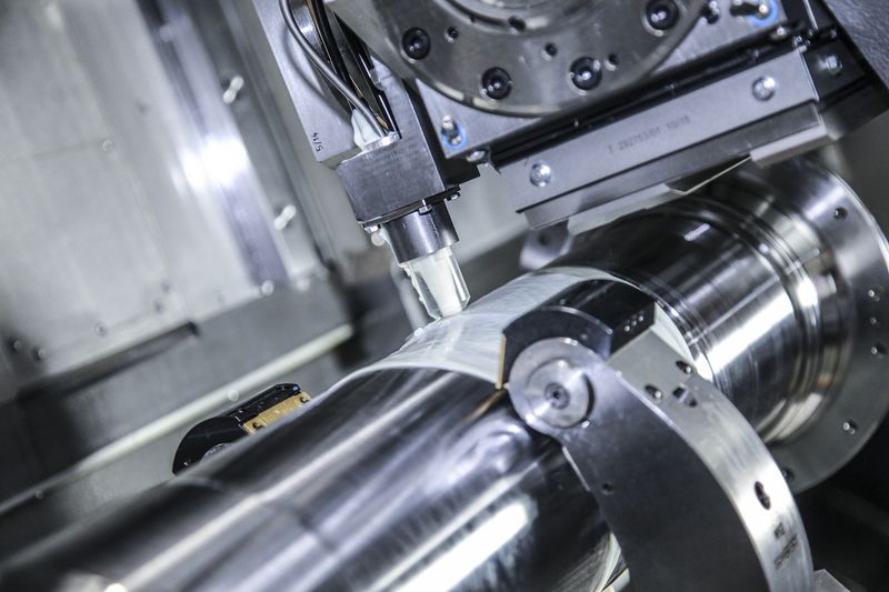
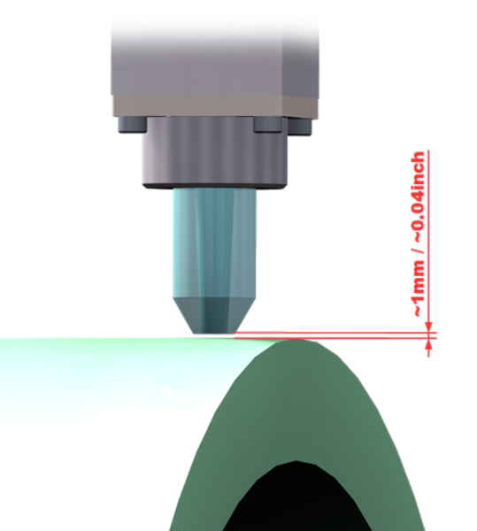
With the help of the ultrasonic measuring device, an ultrasonic signal is transmitted into the workpiece. This signal is reflected in a straight line onto the opposite workpiece surface and is returned to the measuring head. The distance travelled can be calculated on the basis of the time taken for the signal to arrive. In this way, this type of automatic measurement can be used to measure wall thicknesses or inside diameters of pipes quickly and easily without the need for special probes.
The measurement tool is protected by a PVC cover and directs the ultrasonic signals via the cooling lubricant. In addition, the measurement result and all data are displayed in the form of a graph in real time on the operator panel. This means that any material irregularities can be quickly detected and corrected. Typical application areas for ultrasonic measurement are those in the aerospace industry, e.g. for testing engines.
Ultrasonic measurement can be used both automatically and in-process, as well as in semi-automatic mode. Both methods offer the customer a reliable and, above all, intelligent and tailored solution for mastering the machining process.
Automatic ultrasonic measurement
- Ultrasonic wall thickness measurement
- Cooling lubricant is used as coupling medium
- Calibration can be done automatically on the workpiece being measured
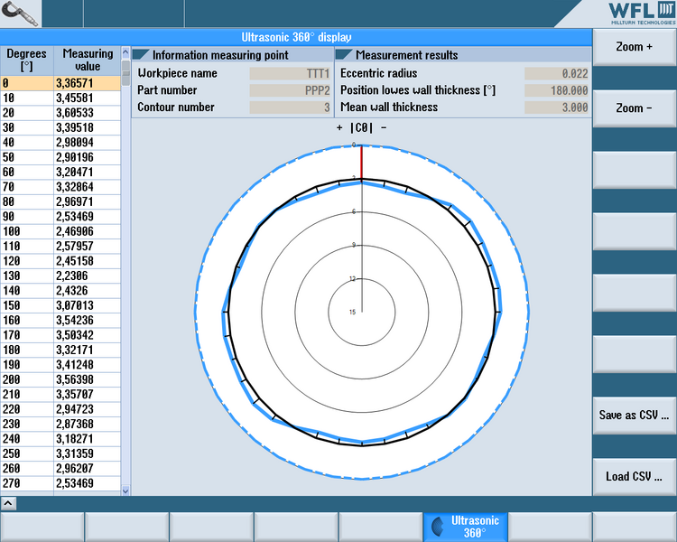
- Wall thickness is scanned through 360° at multiple longitudinal positions
- The position of the centre of the hole is calculated
- Turn-milling of new chip bases concentrically around the centre of the hole
- Remaining machining steps are completed concentrically around the hole
- Typical applications: Drive shafts, landing gear parts (aeronautics), drill pipes (oil and gas)
Semi-automatic ultrasonic measurement
- Ultrasonic wall thickness measurement
- Gel used as coupling medium
- Calibration can be done on the workpiece being measured
- Automatic positioning in relation to the measuring positions
- Manual measuring at 4 measuring points
- The position of the centre of the hole is calculated
- Turn-milling of new chip bases concentrically around the centre of the hole
- Remaining machining steps are completed concentrically around the hole
- Typical applications: Drive shafts, landing gear parts (aeronautics), drill pipes (oil and gas)
WFL measuring cycles
WFL cycles also make it possible to input and calculate the required measured values easily and reliably. Measurement is carried out around the workpiece with 4 measurements every 90° on one or two tape measures. The calculated deviation can be checked for permissible tolerance. The result is the largest deviation in radius and angle. Using these two calculated values from the input fields, it is possible to carry out eccentric clamp position processing.